
How to Design a Welding Fixture Using a 3D Welding Table (Step-by-Step Guide)
- Mar 19
- 10 min read
Updated: Apr 21
How to Design a Welding Fixture Using a 3D Welding Table
If you want faster setups, better repeatability, and more accurate welded parts, learning how to design a proper fixture is one of the most important skills in fabrication.
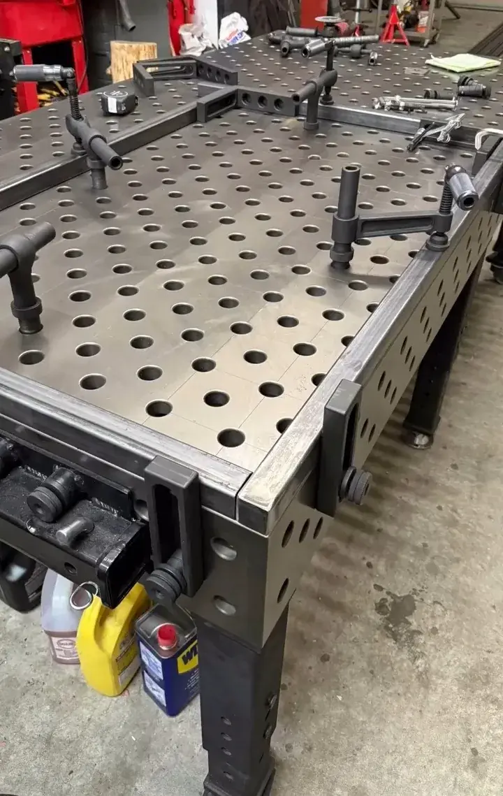
A 3D welding table gives you a modular platform to build fixtures using precision holes, stops, squares, risers, and clamps. Many modern modular systems use a 28 mm hole system with a 100 × 100 mm grid, and 3D table designs allow fixturing not only on the top surface but also on the side faces for vertical and multi-plane setups.
In this guide, I’ll walk through the full process of designing a welding fixture using a 3D welding table, from planning and datum selection to clamping strategy, distortion control, and repeatable production.
To get the best results, it’s important to start with a high-quality 3D welding table that provides a precise and repeatable foundation for fixture design.
What Is a Welding Fixture?
A welding fixture is a setup that holds, locates, and supports parts in the correct position during welding. The goal is simple:
keep the part in the right place
keep angles and dimensions consistent
reduce setup time
improve repeatability from one part to the next
On a modular 3D welding table, the fixture is typically built from the table’s precision hole grid plus standard fixturing elements such as stops, squares, angles, risers, and clamps. Systems like System 28 / 28 mm are commonly used for light to heavy fabrication, while finer systems like 16 mm are often chosen for smaller, more detailed work.
If you're unsure which system to use, read our comparison of D28 vs D16 welding tables to understand the differences.

Why Use a 3D Welding Table for Fixture Design?
A 3D welding table is not just a flat workbench. It is a precision fixture-building platform.
Many modular 3D tables are designed with:
precision-machined hole patterns
five-sided fixturing capability
grid markings for accurate positioning
nitrided or hardened surfaces for wear resistance
side panels for vertical and angle setups
That matters because a good fixture is really about two things:location and repeatability.
When the table already gives you a reference grid and repeatable hole pattern, fixture design becomes much faster and more accurate.
When Do You Need a Welding Fixture?
You usually need a proper fixture when:
you make the same welded part repeatedly
the part has tight dimensional requirements
the assembly includes multiple tubes, plates, or brackets
you need reliable 90° or custom angles
distortion could move the part during welding
manual setup is too slow or inconsistent
For one-off jobs, simple stops and clamps may be enough. For batch production, a dedicated fixture layout saves a huge amount of labor.
Step 1: Start With the Finished Part, Not the Loose Parts
This is the biggest mistake many shops make.
Do not start by asking, “Where do I put the clamps?”Start by asking, “What must be true when the finished welded part is done?”
Before building your fixture, define:
final overall dimensions
critical hole-to-hole dimensions
critical angles
flatness requirements
which surfaces must remain visible or accessible for welding
whether the part must be flipped during welding
the acceptable tolerance after welding
Your fixture should be designed around the critical-to-quality features of the finished assembly.
Example
If you are welding a rectangular tube frame, the key requirements may be:
outside width
outside length
diagonals equal
top face flat
corner brackets held at 90°
That tells you what the fixture must control.
Fixture accuracy also depends on the base surface, so it’s important to understand welding table flatness and tolerance.
Step 2: Choose Your Datum Strategy
A good fixture needs stable reference points. In fixture design, these reference points are your datums.
On a 3D welding table, datums are usually built using:
table edges
hole grid positions
stop blocks
locator pins
angle squares
support faces
The idea is to create a repeatable origin for the workpiece every time it is loaded.
A simple rule
Use one side of the fixture as your primary reference, then build the rest of the setup from that point.
For example:
Datum A = left side stop
Datum B = rear stop
Datum C = support height plane
This prevents the part from “floating” differently every time the operator loads it.
Because modular welding tables use a regular hole pattern and grid system, it becomes much easier to place locators in consistent positions and rebuild the same fixture later if needed.
Step 3: Understand the 3-2-1 Principle
One of the best basic methods in fixture design is the 3-2-1 locating principle.
It works like this:
3 points support the part on the primary plane
2 points locate it on the secondary plane
1 point locates it on the tertiary plane
This reduces unnecessary movement without over-constraining the part.
On a welding table, that might look like:
3 support points under the workpiece
2 side locators against one edge
1 end stop for length
This approach helps you hold the part accurately while still allowing reasonable loading and unloading.
Step 4: Decide Which Features Must Be Located and Which Only Need Clamping
Not every surface needs a hard locator.
This is critical.
A common mistake is trying to force every part edge into a rigid stop. That can make loading difficult and can even introduce stress before welding starts.
Instead, separate fixture elements into two jobs:
Locating elements
These define position.
Examples:
stop blocks
locator pins
angle fences
squares
Clamping elements
These hold the part against the locators.
Examples:
toggle clamps
screw clamps
eccentric clamps
spindle clamps
A fixture works best when locators define geometry and clamps apply holding force.
Step 5: Design Around the Welding Sequence
A fixture cannot be designed in isolation from the welding process.
Before placing every clamp and support, ask:
where will the tack welds go?
where will the final weld beads go?
will the torch have enough access?
will the operator need to reposition the part?
which welds will pull the assembly most?
If a clamp blocks the weld path, the fixture design is wrong.
If the fixture forces the operator to remove supports too early, the fixture design is wrong.
The best fixture is not the one with the most components. It is the one that gives:
stable part location
enough weld access
fast loading
easy unloading
repeatable results
Step 6: Use the 3D Table’s Vertical Faces
This is where a 3D welding table becomes much more powerful than a basic flat table.
Many 3D modular tables allow fixturing on the top and sides, which makes it easier to build vertical setups, support tall frames, and hold assemblies at precise angles. Manufacturer specifications commonly describe these systems as five-sided tables for horizontal and vertical fixturing.
This is useful when you need to fixture:
box frames
cabinets
pipe assemblies
brackets welded at 90°
side-mounted gussets
vertical towers and posts
Practical benefit
Instead of stacking too many blocks on the top surface, you can use the side face of the table as part of the fixture geometry.
That usually improves:
rigidity
accuracy
accessibility

Step 7: Build the Fixture From Basic Modules
Most welding fixtures on a 3D table are made from a few basic building blocks:
1. Support elements
These carry the workpiece.
Examples:
risers
support blocks
spacers
rest pads
2. Locating elements
These establish position.
Examples:
stops
locating pins
fence blocks
squares
3. Holding elements
These keep the part in place.
Examples:
clamps
bolts
eccentric locks
push-pull mechanisms
4. Verification elements
These help confirm the part is loaded correctly.
Examples:
gap checks
edge references
diagonal measurement points
angle references
When designing, always try to use the fewest parts necessary to achieve repeatable loading.
Too many fixture elements slow down the operator and increase setup complexity.
Step 8: Control Height Carefully
Many welded assemblies fail inspection because of height inconsistency, not just length and width.
If you are building on a modular welding table, use the table surface as your primary height reference and then control additional heights with:
equal-height support blocks
machined spacers
risers
angle brackets with known dimensions
For example, if a crossmember must sit exactly 100 mm above the table plane, do not “eyeball” it with random shims. Use fixed-height supports.
The more standardized the support heights are, the easier it becomes to reproduce the fixture later.
Step 9: Think About Heat Distortion Before You Weld
A fixture should not only hold a part in the correct shape before welding. It should also help the part stay within tolerance after welding.
Weld shrinkage can pull:
corners inward
long tubes into bow
plates into twist
brackets out of square
Ways to reduce this in your fixture:
support the part close to weld zones
clamp near critical joints
use symmetrical tack points
avoid excessive force that preloads the part
leave access for balanced weld sequencing
use hard locators on critical dimensions only
For long frames, add support under the length so the assembly does not sag while being tacked.
For corner assemblies, make sure the 90° locating element is rigid enough to resist pull during tack welding.

Step 10: Design for Operator Speed
A fixture that is accurate but slow may still be a bad fixture.
In real production, fixture design should reduce:
operator decisions
measuring time
re-clamping
adjustment
Ask yourself:
Can the operator load the parts in one obvious way?
Are left/right parts easy to distinguish?
Are clamp handles accessible?
Can the fixture be cleared quickly after welding?
Can slag and spatter be cleaned easily?
This is one reason hardened or nitrided modular table surfaces are popular: manufacturers market them for improved wear resistance and durability in repeated shop use.
A fast fixture is not just about speed. It also lowers operator error.
Step 11: Plan for Inspection
The best fixtures make inspection easier, not harder.
When designing your setup, leave room to check:
diagonals
critical center distances
edge offsets
hole positions
angle accuracy
Do not trap every side of the part if one of the key dimensions must be measured before removal.
In some fixtures, it helps to design in a simple inspection window:
an open side for a square
a visible gap reference
a fixed measurement point from table grid lines
Some modular tables include scale markings and grid lines specifically to assist accurate positioning and construction.
Step 12: Prototype the Fixture Before Finalizing It
Even if you already know the part well, do a dry run.
Build the fixture loosely, then check:
can every component be loaded smoothly?
does any clamp interfere with the torch?
does the part rock or shift?
is anything over-constrained?
is unloading easy after weld tack?
Make changes before you standardize the setup.
This step can save a lot of wasted production time.
Example: Designing a Fixture for a Rectangular Tube Frame
Let’s walk through a simple example.
Part
A rectangular steel frame made from square tube, with two crossmembers and four corner joints.
Critical requirements
outside size must stay accurate
corners must be square
top surface should remain flat
repeated batches of 20 parts

Fixture strategy
1. Primary support
Use the table top as the main reference plane.
2. Length and width stops
Install two perpendicular stop lines using modular stops or squares.
3. Squareness control
Use a precision angle square at one corner and verify diagonals before final tack.
4. Height support
Use equal risers for the crossmembers so all components sit in the same plane.
5. Clamping
Use clamps to press the tubes against the stops, not to bend them into place.
6. Welding access
Leave the inside corners open enough for tack welding and final weld passes.
7. Distortion control
Tack opposite corners first, then crossmembers, then verify dimensions before full welding.
This kind of setup is exactly where a modular 3D table shines, because you can rebuild the fixture precisely using the hole grid and standard locating components.
Common Fixture Design Mistakes
1. Too many clamps
More clamps do not always mean more accuracy. They often make loading slower and block welding access.
2. No clear datum
If the part can be loaded in slightly different positions each time, repeatability is lost.
3. Over-constraining the part
A fixture should locate the part, not fight against natural fit-up variation so hard that it introduces stress.
4. Ignoring weld pull
If distortion is not considered, the part may be perfect before welding and wrong after welding.
5. No allowance for operator access
Clamp handles, torch angle, and part removal must all be considered.
6. Designing only for one perfect part
Real fixtures must tolerate normal production variation.
Best Practices for 3D Welding Table Fixture Design
Here are the habits that usually produce the best results:
start with the finished-part requirements
establish clear datums
use 3-2-1 locating logic
separate locating from clamping
leave room for welding and inspection
keep the fixture simple
use the side faces of the 3D table when needed
design for repeated loading
standardize support heights
document the final setup
Because many 3D systems are based on standard borehole sizes and a regular grid, documenting your hole positions and fixture stack-up makes future repeat jobs much easier.

Why a 3D Welding Table Improves Fixture Design
Compared with a plain steel bench, a modular 3D welding table gives you:
faster setup changes
repeatable hole-based positioning
multi-face fixturing
better use of modular stops and clamps
easier standardization for repeat jobs
On official product pages, manufacturers commonly describe these systems as heavy-duty modular tables with 28 mm boreholes, 100 × 100 mm grid spacing, and vertical/horizontal fixturing capability, which is exactly why they are so useful for fixture design.
Final Thoughts
A good welding fixture does not have to be complicated.
The best fixture is the one that helps you:
load parts quickly
hold them accurately
weld them consistently
repeat the result every time
If you use a modular 3D welding table correctly, you can turn fixture design from a slow trial-and-error process into a repeatable system that improves both quality and productivity.
For fabrication shops in Canada, this is one of the biggest advantages of using a modular D28 3D welding table system: it gives you a precise platform for both one-off custom jobs and batch production setups.
FAQ Section
What is the main purpose of a welding fixture?
A welding fixture holds and locates parts so they stay in the correct position during welding, improving consistency and reducing setup time.
Why use a 3D welding table instead of a flat welding bench?
A 3D welding table gives you a precision hole grid, modular fixturing options, and side-face setup capability for vertical and multi-plane assemblies.
What hole system is common for heavy-duty modular welding tables?
A common heavy-duty modular format is 28 mm holes with a 100 × 100 mm grid, used in many System 28 style tables.
How do I make a welding fixture repeatable?
Use fixed datums, standard locator positions, controlled support heights, and documented hole locations on the table.

Ready to Build Your Welding Fixture Faster?
If you're planning to design a welding fixture using a 3D welding table, choosing the right system makes all the difference.
We help fabrication shops across Canada:
Select the right welding table size (D16 / D28)
Recommend complete fixture setups
Provide drawings within 24 hours
Calculate shipping cost to your location
👉 Get a fast quote today and start improving your production efficiency
📱 WhatsApp: +86 180 2874 2690


Comments